Saturday, March 4, 2017

My Experiences as a Beginner Woodworker (, , ,)


Woodworking takes time! It’s not something that can be rushed or perfected on the first try. It requires practice and learning from your mistakes. In the end, you end up with a beautifully crafted object that you can call your own. 

The experience of creating something out of nothing is extremely rewarding.

The experience of creating something out of nothing is extremely rewarding. That’s also one of the reasons whyI love computer science. The fact that I can create something that can reach millions of users. 

I began my journey into woodworking a few days before my sister’s birthday. As I tend to do with most birthdays, I start thinking of what gift to get a couple days before hand. My sister recently started getting interested in the startup culture and began watching Silicon Valley. When you combine these interests together, you get your sister a 1 month subscription to HBO… hiding the fact that it was just a free trial. 😜 

Only joking! This is where the three commas (, , ,) come in…
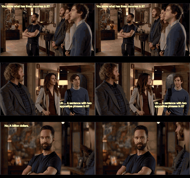
Three Commas Club (THrē ˈkäməs kləb)
Three commas to imply a billion dollars as $1,000,000,000 has 3 commas. To be in the three commas club is to be a billionaire. [source]

I wanted to get her something that represents the three comma club, pushing her to achieve her entrepreneur focused goals. While there are many t-shirts and paintings of three commas, I set out create them out of wood. Something that can be placed on her desk of her future unicorn. 🦄 

It’s Woodworking Time!

Sketch It Out

When you get started, you have to have a sketch. Whether it’s on a napkin or a sheet of paper, get your ideas down in some physical form. It’s difficult to create something from scratch when it’s just in your head. 

The same can be said for software engineering. You have to create a rough architecture diagram so you have a reference point.

I started by sketching on a sheet of paper and moved on to creating a digital version of it:

three commas sitting on a base

Drawing a large comma on a sheet of paper is actually harder than I thought. It was easier to create a digital version of the sketch since I could work off a preexisting image of a comma.

I used Sketch to design my digital commas and worked off of an image from TheNounProject.

Technically yes, the sketch above would not be physically possible due to the center of gravity being located towards the right. The comma would just fall/roll over on it’s side. I ended up using a different edge for the base in my final designs. However this was still an issue and had to update my designs to take that into account. (will get into this later)

My Setup
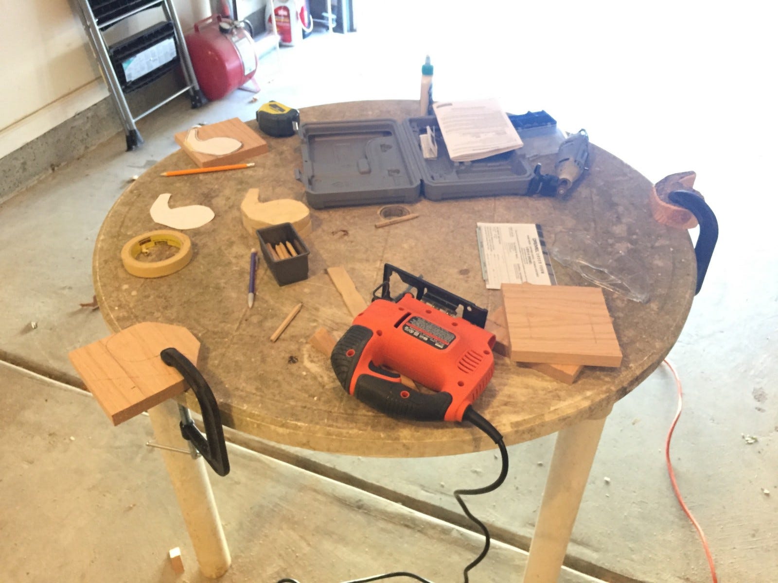
Unfortunately I did not have an official wood working table. I ended up using an old plastic picnic table. It was not ideal but it got the job done.

Initial Tools & Materials 

Also, if you are me, you have almost zero materials for working with wood. There’s many different opinions on how to get started but this is what I did.

I bought a cheap jigsaw ($30), two clamps, and sandpaper (60, 120, 220 grit). I already had an extra table to work on but make sure you have a good flat surface where you can easily clamp your wood to.

If I had known about jigsaw blades earlier, I would have bought a separate set of jigsaw blades when started this project. Not all blades are alike. Some blades are good for curved cuts, others are good for smooth cuts, and etc. The jigsaw comes with a default blade.. which gets the job done. However the blade specifically for curved cuts was phenomenal. It was easier to direct the jigsaw around curves and it usually came out with a smoother finish.

I’ll have information about what materials and tools I used scattered throughout this post. To see a complete list and additional details, scroll to the end.

Start with Practice Wood

If you have never worked with wood before, get some practice wood from Home Depot or Lowes. I started out with a 2in x 4in x 8ft block of pine wood ($5). 

Pine wood is extremely easy to work with since its soft wood that can be easily shaped. It also helps that its extremely cheap. Check out this site for more information on pine and other kinds of wood: link.

Initial Cuts

Begin by drawing an outline of your designs on the wood. Preferably with a pencil. Unfortunately, I lacked the insight and used a sharpie :/

Use the jigsaw to make rough straight cuts. Going in straight lines made it easier than going around curves. I made many passes and continue shaping down to the outline over each cut.
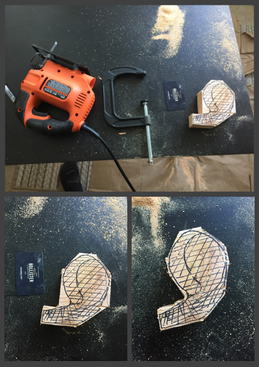
As you can see above the cuts are very rough. However it is possible to get somewhat of a finished look if you can work carefully with a jigsaw. The blades made for doing curved cuts will help a lot towards getting that finished look. Which is what I ended up using for my final pieces.

Try to get a hang of the jigsaw when using your practice wood. Also sand it down with sandpaper and the dremel to get a feel for the tools & materials. You want to have a good idea of how to cut with a jigsaw and sand with a dremel before you move on to your real wood. 

Creating the Commas

After I had gotten a hang of the tools on pine wood, I moved on creating to creating my commas out of oak. I used oak because it was an easy to work with hard wood that has a more premium look to it. I also wanted it to be stained and not painted. 

Unfortunately the oak did not come in 2in thick wood, which is how thick I wanted my commas to be. So I ended up using two 1in pieces and glueing them together. 

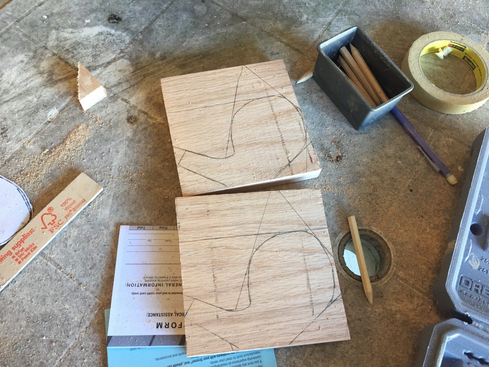
As I did with pine wood, I started off outlining the designs on the wood. Again, do not eye ball this as a beginner, these are your reference points.
Entire Cutting Process

Just to understand the entire cutting process, this is what it looked like from start to finish.
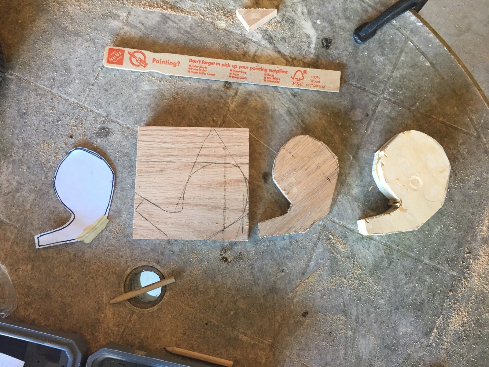
  1. Creating the sketch
  2. Drawing the outline
  3. Cutting along the outline
  4. Glueing two pieces together

Glueing 

After cutting each comma piece, I applied wood glue on both of the pieces and clamped two of them together. I believe the wood glue says to wait for 60 mins but I left it for a few hours.
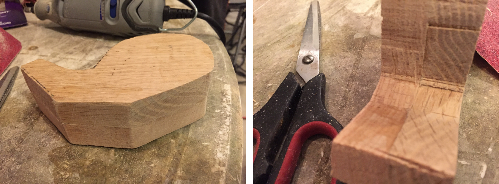
Make sure the glue comes out the sides and wipe it clean. This way you have a clean edge and no gaps between the two commas. However, do not fret if there are gaps, you can use wood filler to fill it in. 

After glueing them together, I had to use the jigsaw again to get the two pieces flat and lined up properly.

Sanding

After cutting/glueing, I sanded down the wood. However I wished I had sanded after I applied the wood filler. Mainly because I had to sand another time.
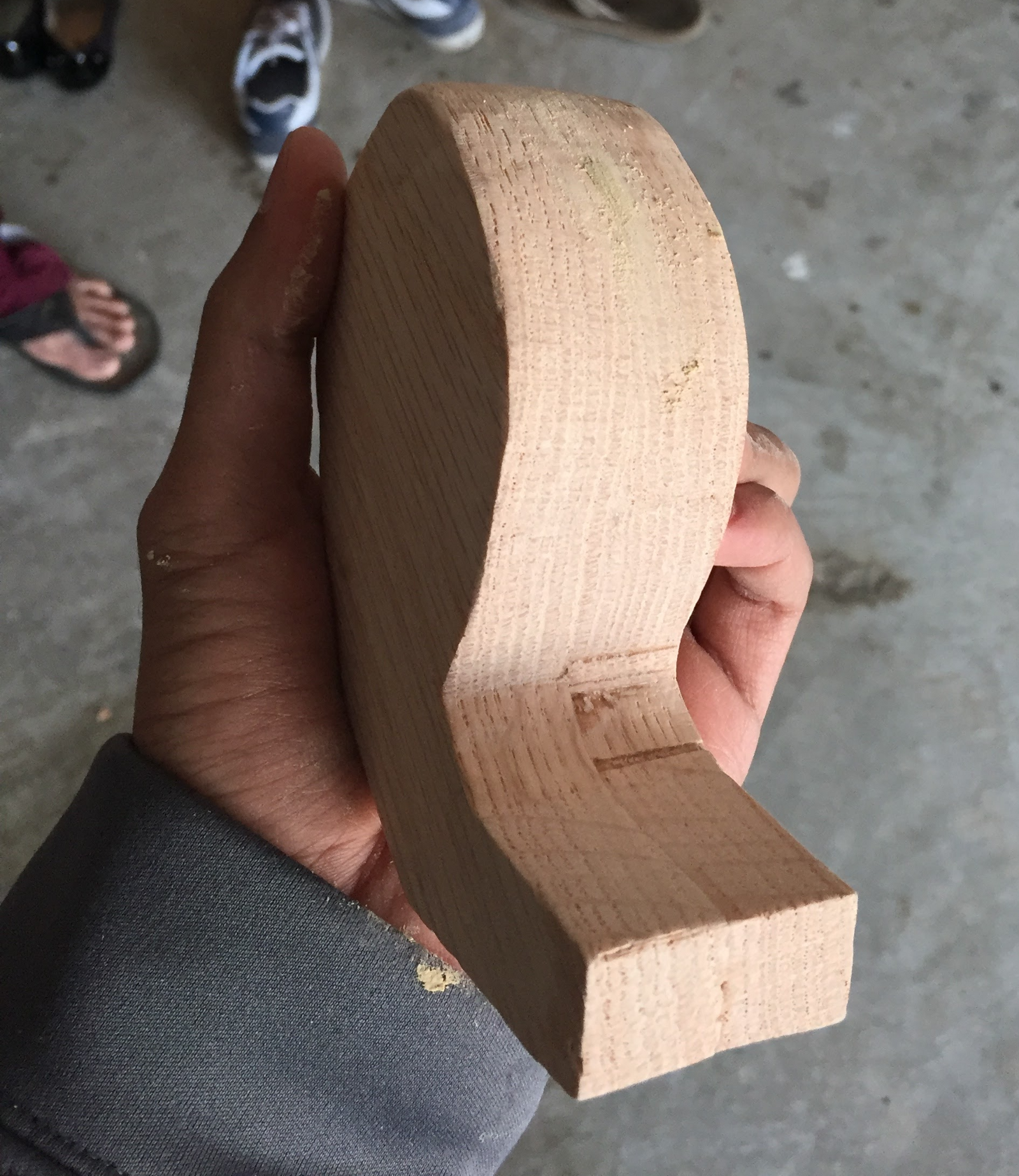
When sanding, start from an extremely coarse sandpaper (60 grit), then move on to finer sandpaper. So I sanded the commas with 60 grit, then moved to 120 grit, and then finished with 220 grit.

I thought I could sand with the dremel but I did not realize the dremel was for sanding smaller areas and touching up finer details. I ended up sanding by hand and finishing with the dremel. The dremel was used to sand the inside curves of the commas as that was not easy to do by hand. However, you could buy belt/disk/orbital sanders to sand larger pieces.

Touching Up

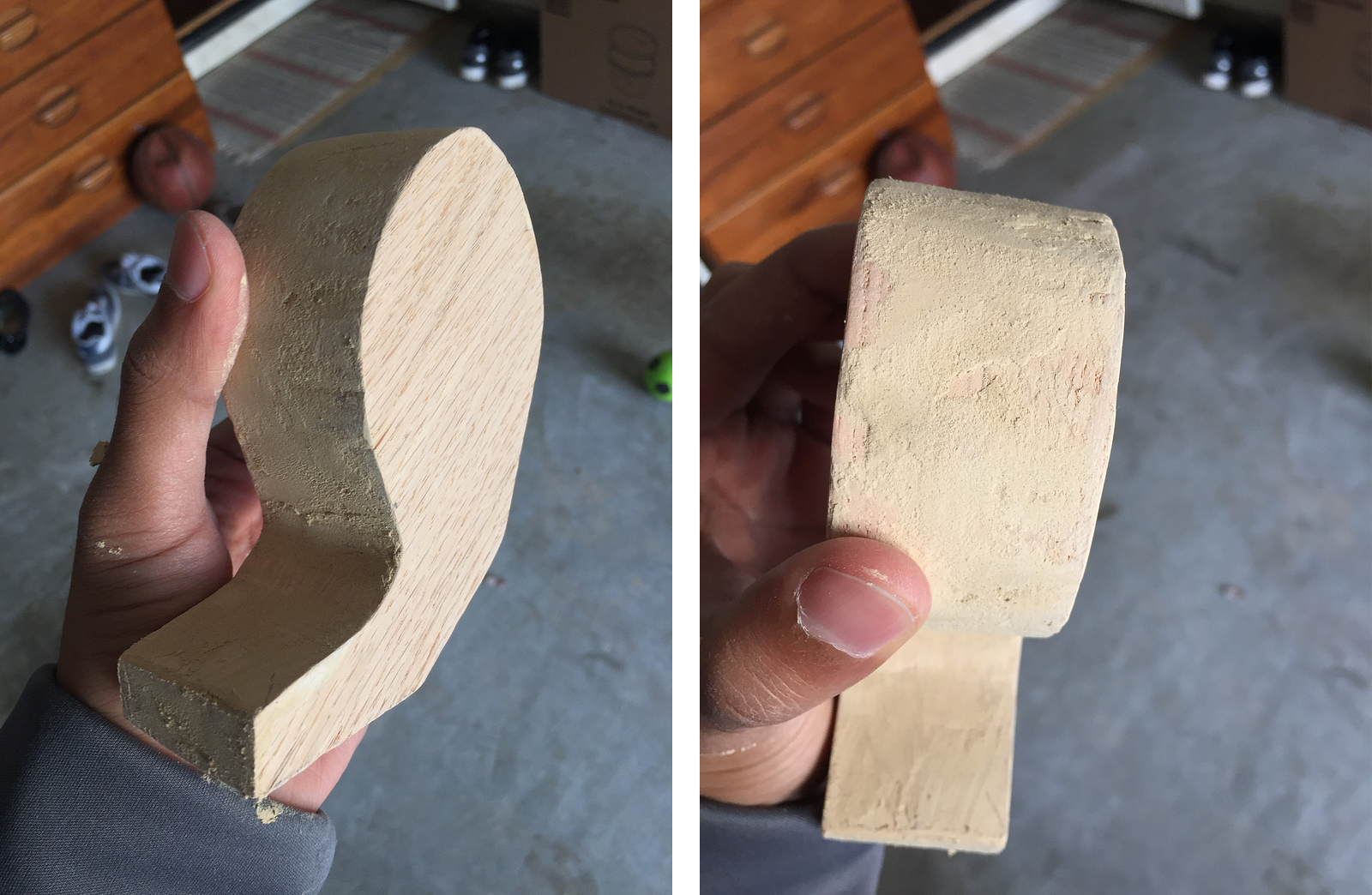
As I said, I used wood filler to fill in any gaps between the wood and any mistakes that happened while cutting. The specific filler I used was Plastic Wood 3 oz. Natural Latex Carpenter’s Wood Filler.

It does look a little rough, however you can sand it down after it dries. In addition, if you get the natural colored filler, you can also stain right on top of it.
Staining Wood

I chose to stain the wood instead of painting it. Mainly because I wanted the wood grains to show. 

I used Red Mahogany Wood Stain.When picking out a wood stain, make sure to ask to see the stain samples. You can get a good idea for how the color dries on wood.

I cut up an old white cotton t-shirt and used that to stain the wood. I won’t go into how to stain the wood as the instructions are right on the can. Just make sure to be in an well ventilated area as the smell is pretty strong.
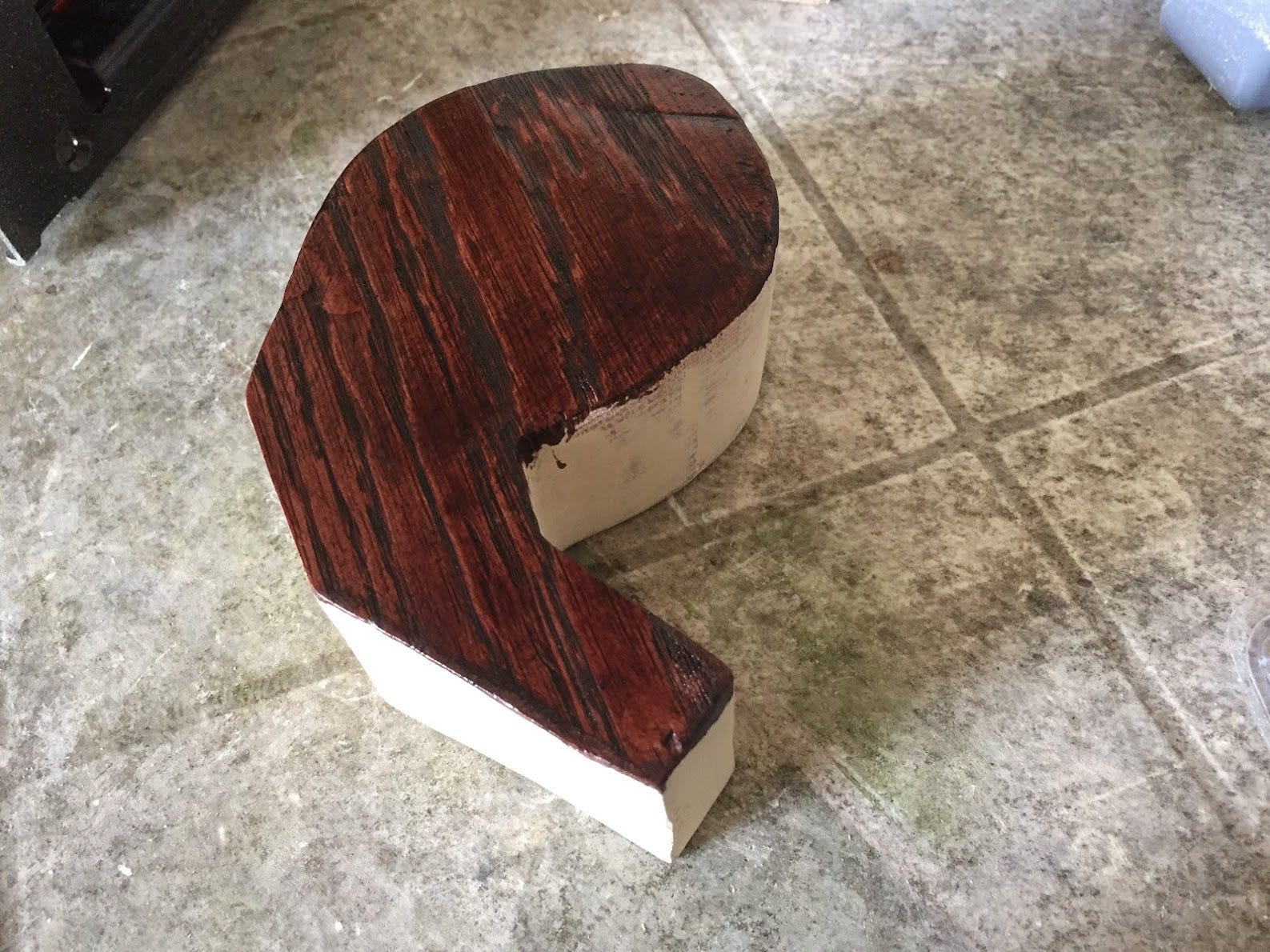
This took the longest as I had to stain each side and wait for it to dry a couple hours before I could apply another coat.
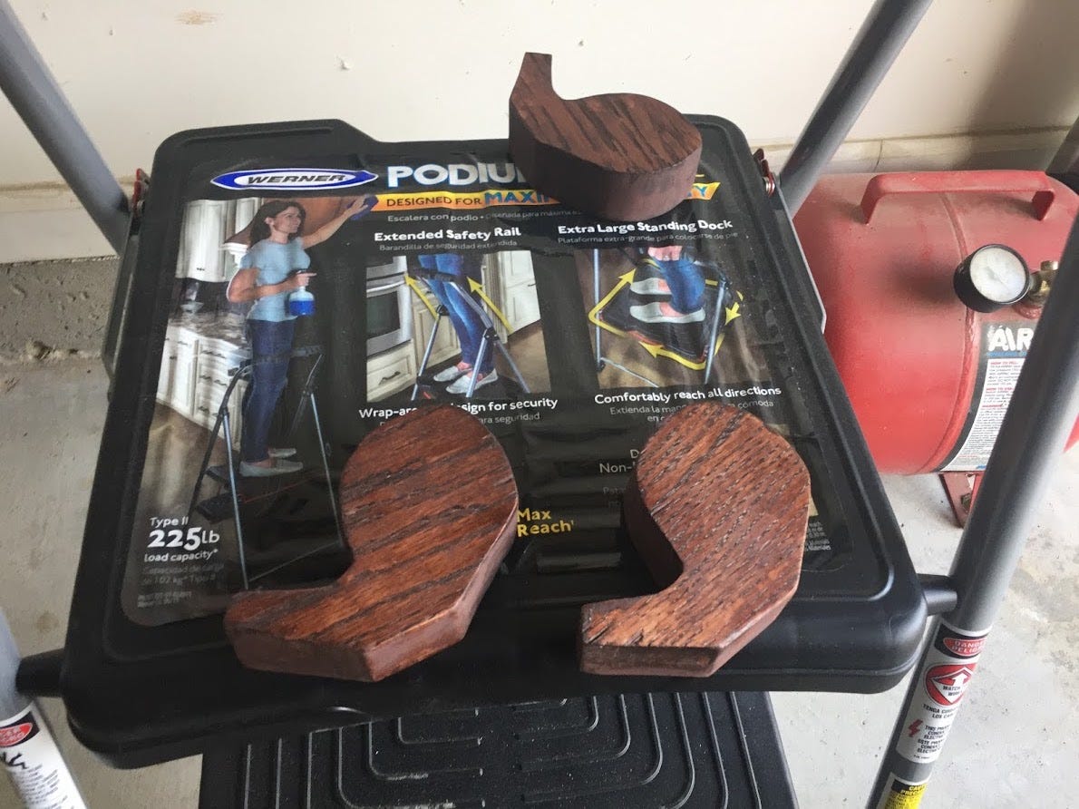
Staining Wood (Problems)

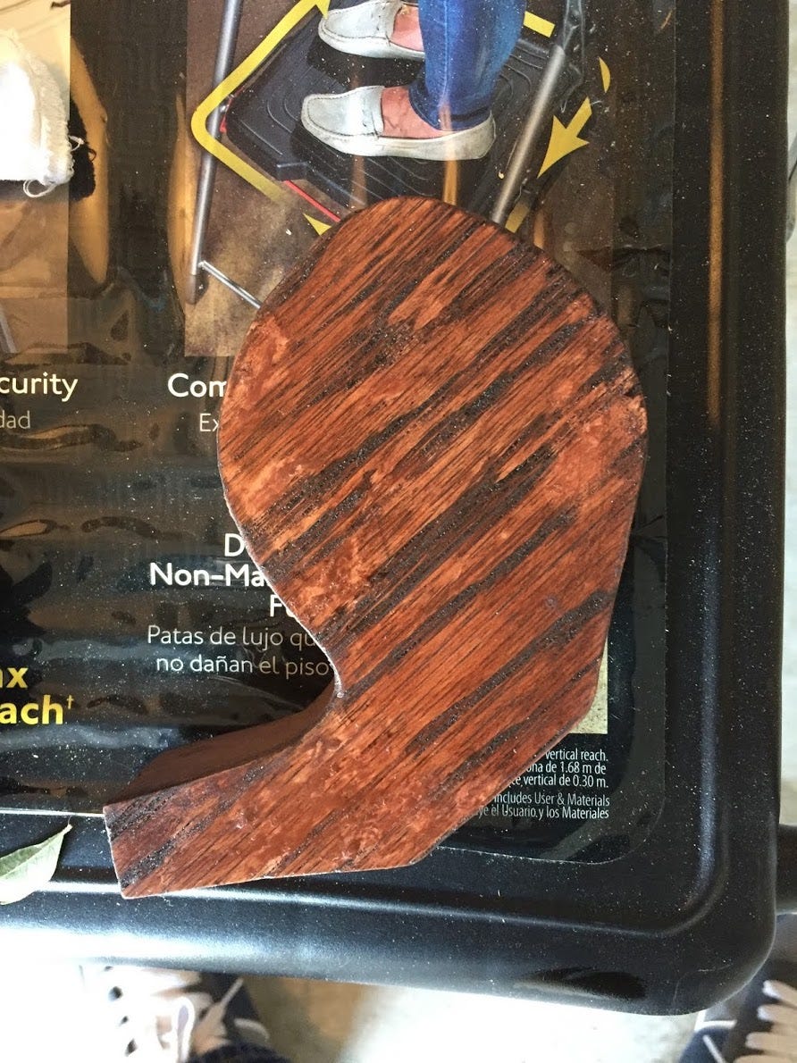
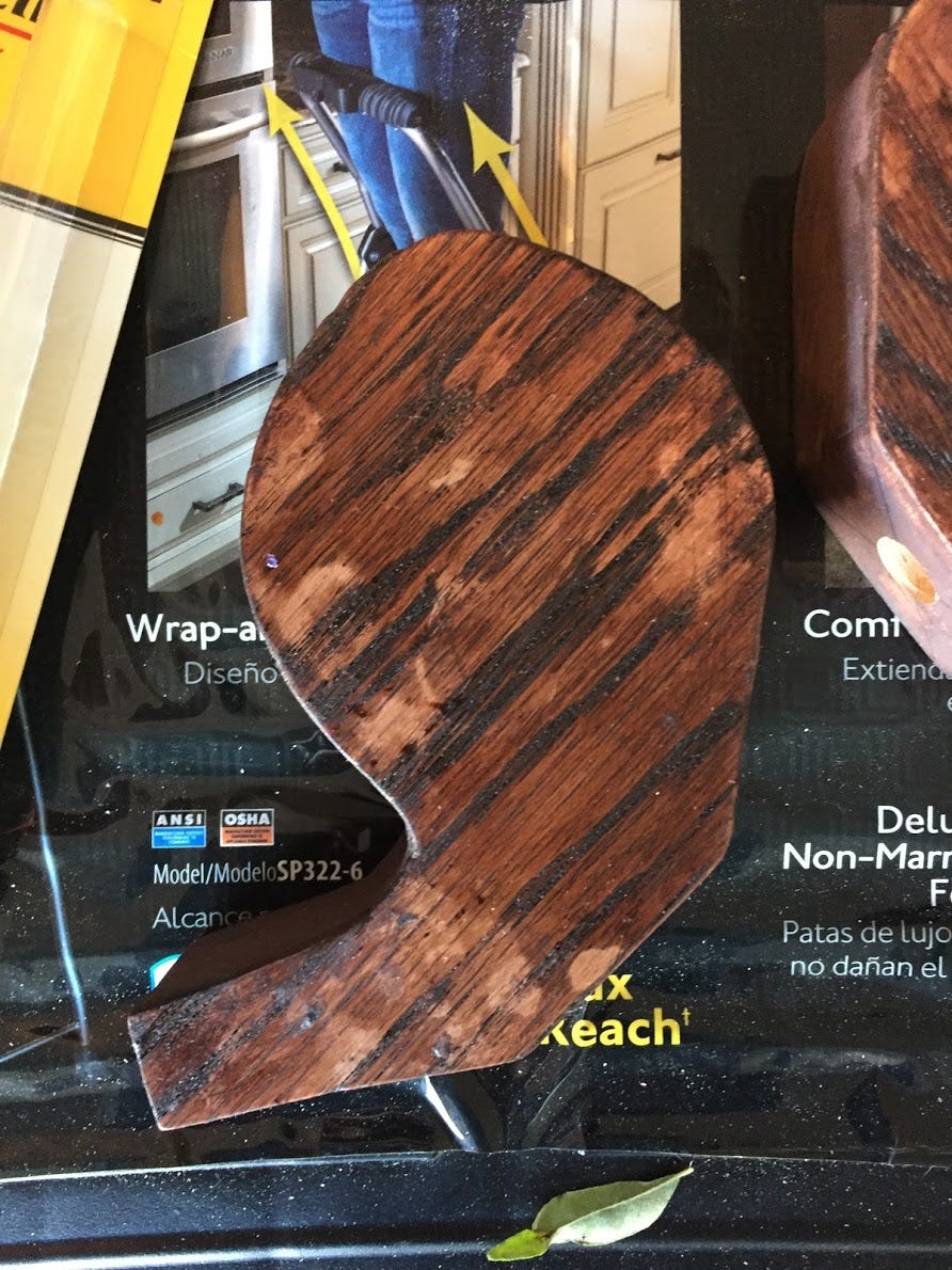
Unfortunately some of my wood stain dried in blotches/patches. See below.
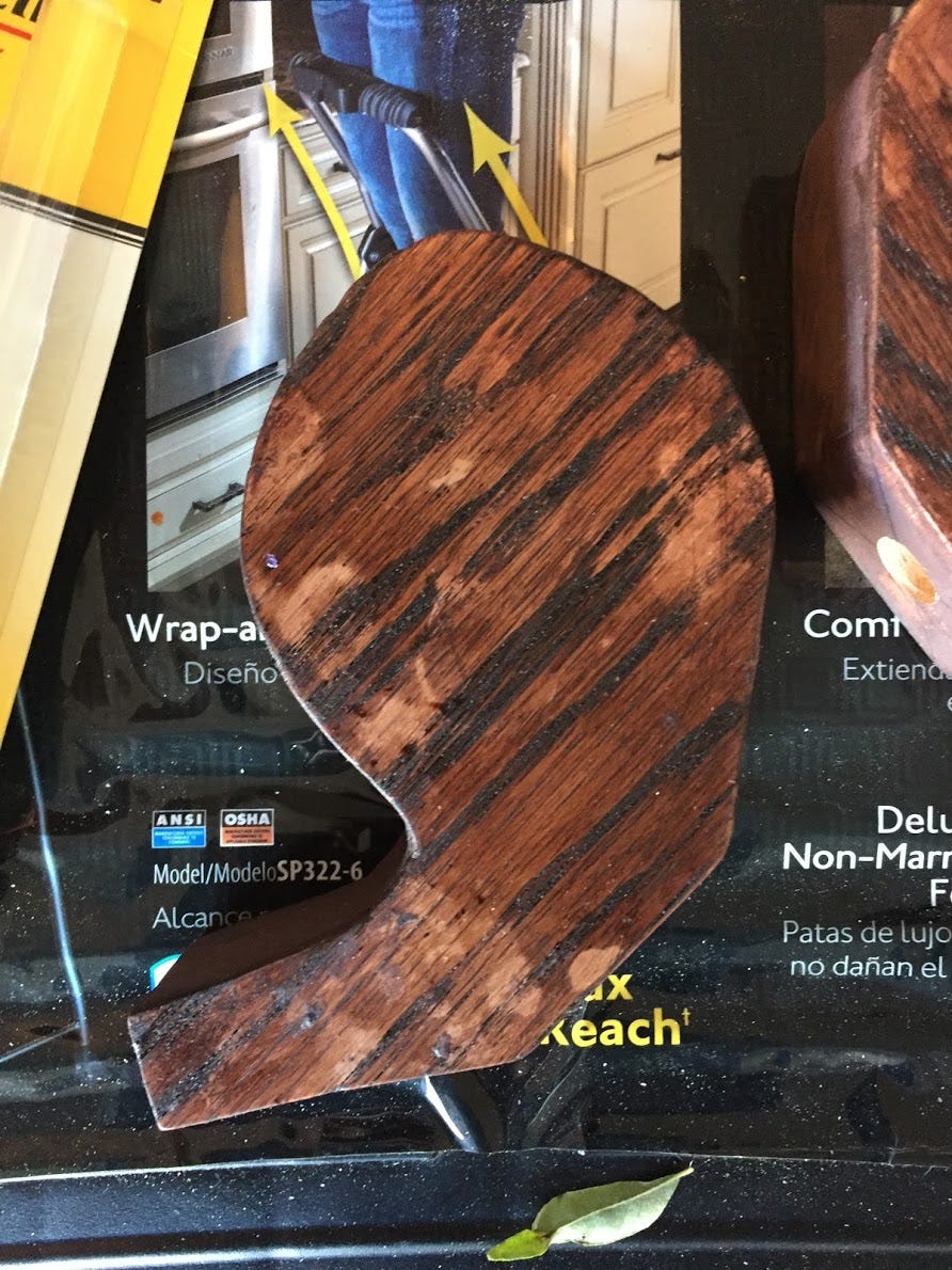
I could never figure out why this actually happened but I do have one theory. The instructions on the can state that you should apply the stain, wait for it to soak in for a few mins and then wipe of the stain completely. Maybe I had applied or wiped off the stain unevenly. With this theory in mind, I tried staining only the blotched areas again but that did not do anything.

A suggestion from the Home Depot associate was to use pre wood stain conditioner as this would allow for wood to be stained evenly at all times. However this required sanding/removing the current stain and then re-staining. 

Unfortunately I did not have enough time to do that, so I ended up using a Red Mahogany Blend-Fil Pencil to fill in the blotched areas. Ideally, these should be used for touchups. They do not work well for large areas. In my case, the blotches still existed but the pencil made it less noticeable.

TK(wood-stain-blotches-1-img and woodstain-blotches-fixed-img)

Top Coat

After the stain had dried, I applied a topcoat (polyurethane, semi gloss) for a layer of protection and gloss. The stain layer also felt a little unfinished so the topcoat helped give a more smoother feeling to the commas.

Building the Base

I used some extra oak wood that I had to build the base. The base was pretty straightforward; it’s a plain block of wood. I wanted to add some depth to it so I used the router bit on the dremel on the edges of the wood.
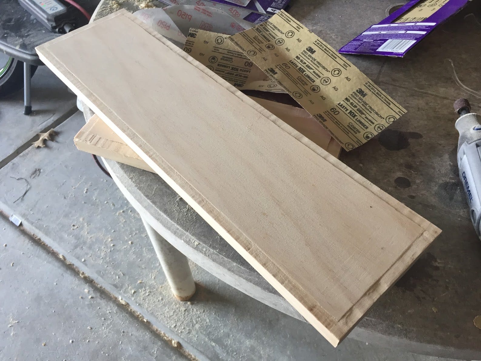
I was free handing it so it was difficult to get a straight even cut all the way across. If I had something to rest the dremel on to get that even cut, it would have come out better. 

After cutting and sanding the base, I moved on to staining it with a lighter stain. Luckily the stain didn’t dry blotchy as it did for the commas.
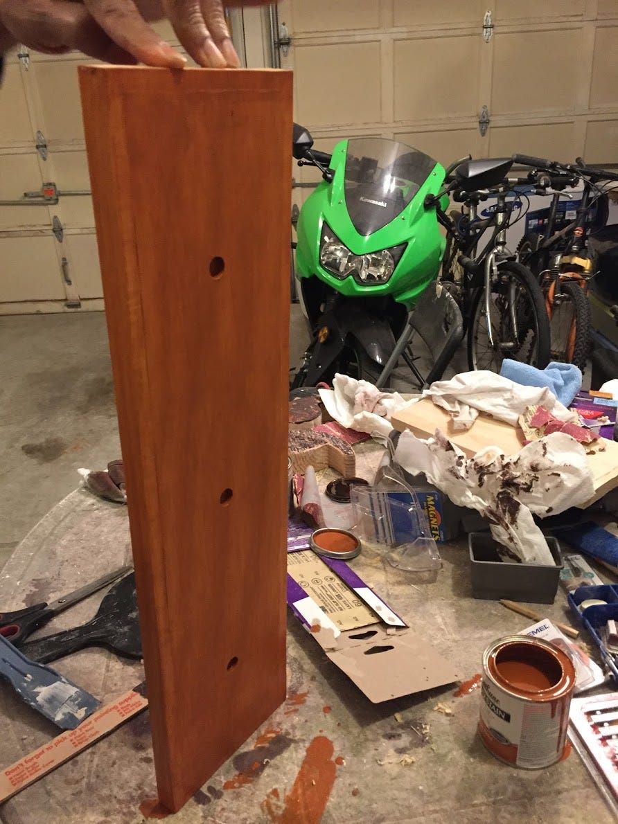
I finished off by applying a layer of topcoat to the base as well.

Sitting the Commas on the Base

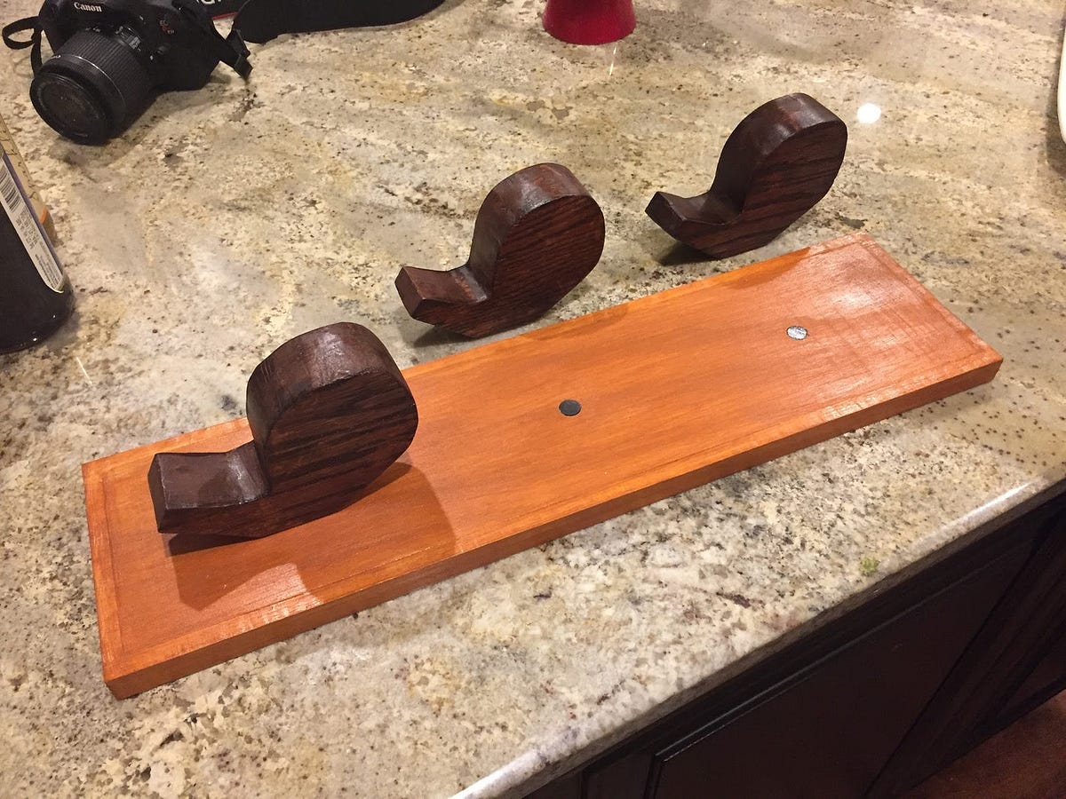
Getting the commas to sit on the base on its own was difficult. The commas would roll over as the center of gravity was toward the right.

There are a few solutions to this but in the end I used 1in circular magnets on the bottom of the commas and on the base.
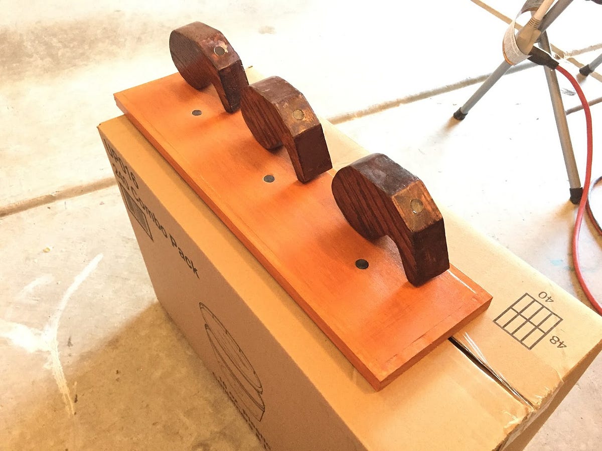
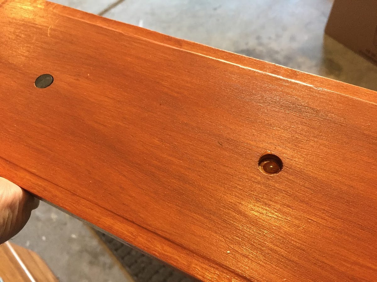
To fit the magnets, I had to drill holes using fornester bits on both the commas and base and used gorilla glue to glue the magnets inside the holes.
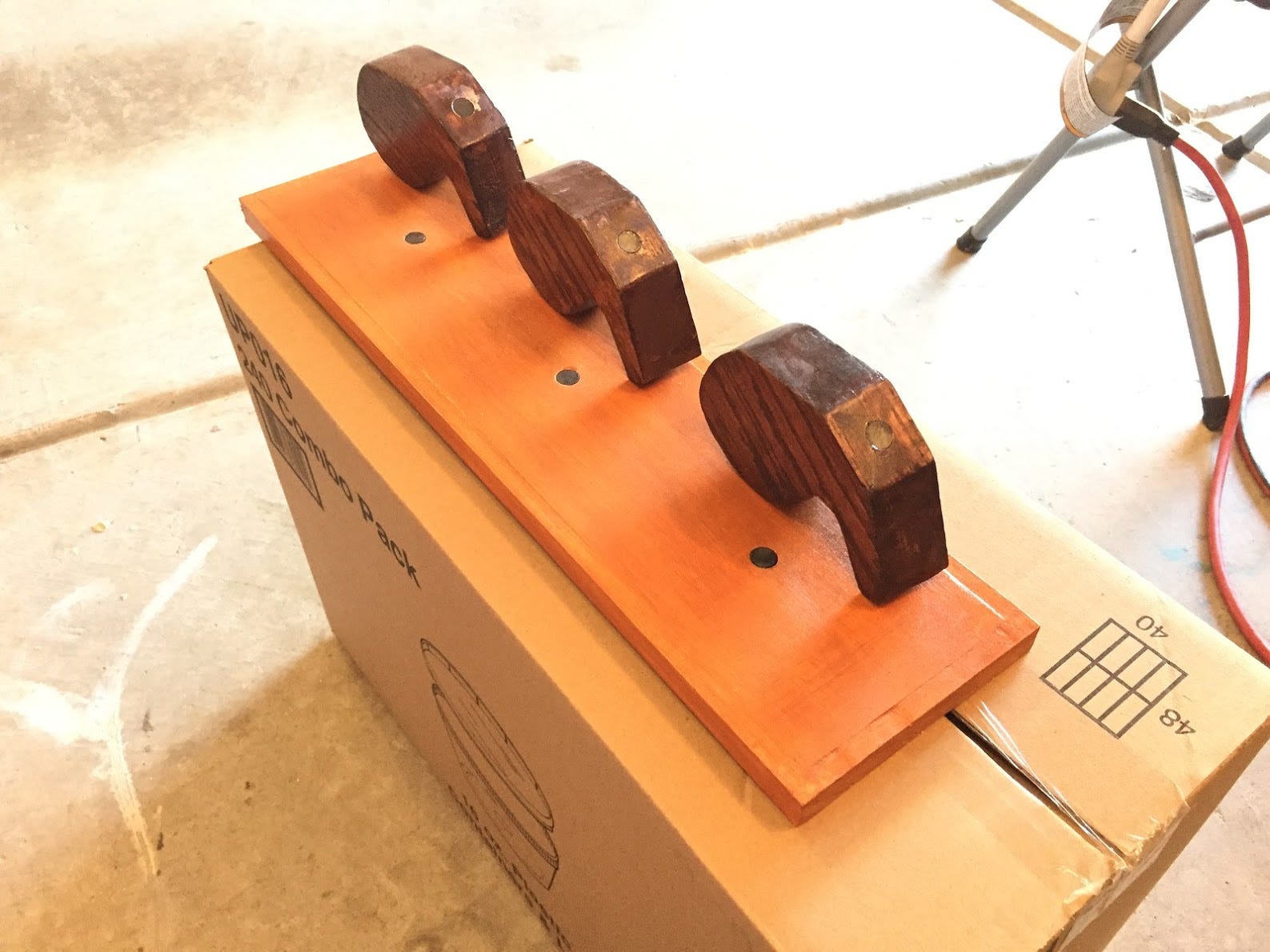
Like I mentioned, there are other solutions. One could secure the commas/base permanently by using screws/nails. However I wanted the commas to be removable and re-postionable. TK(fix word)

Finished Commas & Base

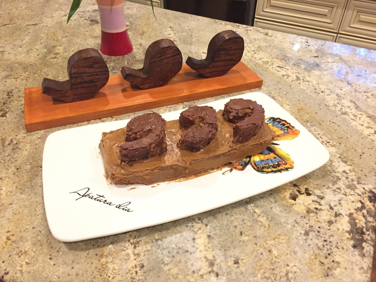
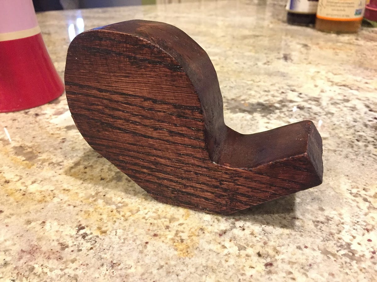
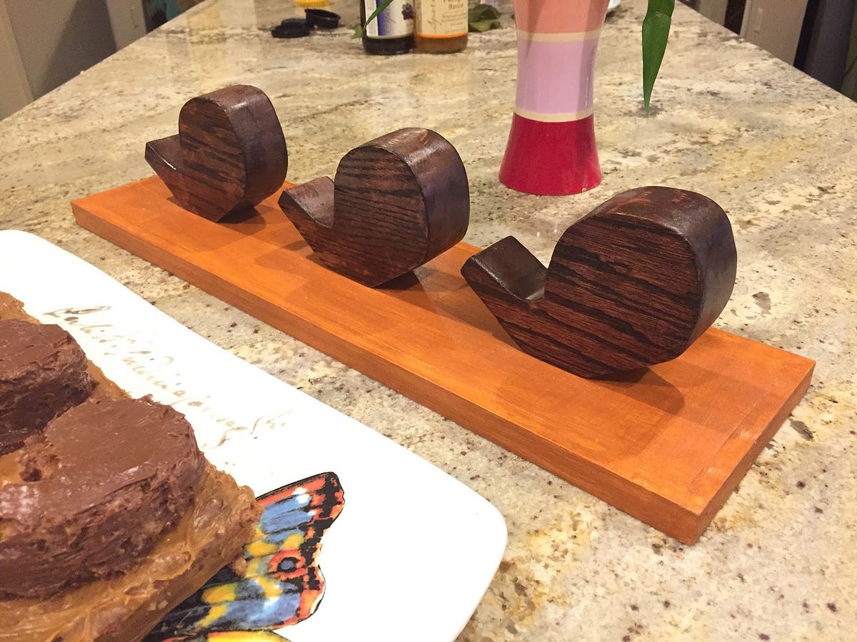
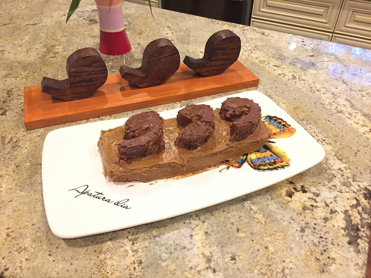
All in all, everything somehow came together. The magnets worked perfectly to hold the commas on the base. The stain showcased the grain beautifully (disregarding the blotchy areas). We also baked a three comma cake since this was for my sister’s birthday.
Materials
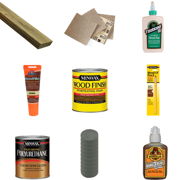
materials that I used, see below for more info
  • Pine (Regular & Premium) and Oak
    Used pine for practice. Moved on to premium pine and oak for the final object.
  • Sandpaper (60, 120, 220)
    It’s recommended to start with a lower grit sandpaper and gradually move on to higher grits. 
  • Wood Glue
    My oak wood was 1 inches thick but I wanted my commas to be 2 inches. I ended up cutting two commas and glueing them together.
  • Wood Filler
    Had to use wood filler to fill up mistakes while cutting.
  • Wood Stain
    This is stain. Not sure what else can be said about stain. Make sure to use this in a well ventilated area.
  • Blend-Fil Pencil
    The stain came out blotchy and patchy on two commas. Not sure why. The home depot guy recommended to use pre wood stain conditioner next time. The Blend-Fil Pencil is like a crayon on which you apply onto small imperfections. It didn’t work perfectly in my scenario.
  • Topcoat (Polyurethane, Semi-Gloss)
    Top of the mornin to you lads. Finishes your wood. Adds a layer of protection and gloss.
  • Magnets (0.5 in diameter)
    A magnet was placed on the bottom of the comma and on the base. This allows for the commas to stay upright.
  • Gorilla Glue
    Gorilla glue was used to glue the magnet to the hole/base.

Tools
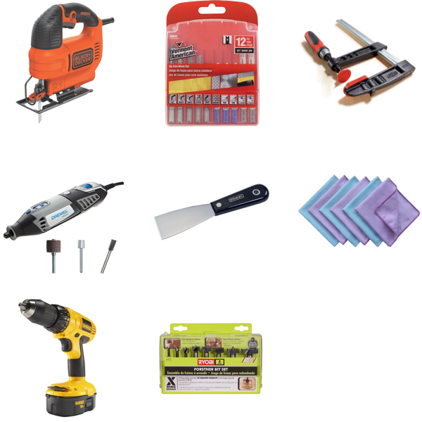
tools that I used, see below for more info
  • Black and Decker Jigsaw
    A cheap $30 jigsaw. Good for rough cuts on wood.
  • Additional Blades for the Jigsaw
    The jigsaw comes with a blade however I had not known that there different types of blades for different functions (e.g. cutting on a curve or wanting a fine finish). So if you are looking to do any complex curved cuts, get the blade for curved cuts. I found this out a little late but it helped me tremendously!
  • Clamps
    Again, not too much to say about clamps. Just make sure to get one to hold your wood in place while doing the cuts.
  • Dremel 4000 + Sanding, Carving, and Routing Bits
    Good for finishes. However not for large jobs. I ended up sanding most of it by hand. Only the inside of the commas I sanded using the Dremel. 
  • Putty Knife
    Used this to apply the wood filler. You could also do this by hand but you will get a smooth application if you used this.
  • Lint Free Cloth/Old T-Shirt
    This was to apply the wood stain and top coat. I just used an old t-shirt.
  • Power Drill
    This was used in combination with the fornester bits.
  • Fornester Bits
    The fornester bits were used to drill flat holes in the bottom of the comma and the base.

Shoutouts

A big shout out to…
@boland and @jmanweiler for giving me tips on how to get started!
@my dad: since I was home for the holidays, he helped out with creating the commas.
@my mom: for baking an amazing three comma cake


Monday, December 29, 2014

MagPen - A Novel Way of Digitizing Notes Using Magnets

MagPen Software

A mobile device has a multitude of sensors ranging from GPS to a barometer. One sensor that is used daily is the capacitive sensor. Capacitive sensors detect anything that is conductive and they are used for touch input in mobile phones. We rely tremendously on touch input to interact with our devices ranging from playing games to checking notifications. We also have the ability to use our finger or styluses to write notes directly on a mobile device. However, touch/stylus input on mobile devices has its own set of problems. We are unable to easily draw detailed diagrams or write notes using the touch screen.

Is there another way to provide a different method of digitizing notes with a mobile device that expands the capabilities of touch? Another sensor that can be used for alternative methods of interaction is a magnetometer. The magnetometer senses changes in the magnetic field in all three axes (x,y,z) [10]. If the magnetic field can be detected, then it is possible to alter the magnetic field by using an external magnet. When the external magnet is moved around, it will alter the magnetic field thus producing different (x,y,z) values.

MagPen Software

MagPen is a system that allows the user to digitize notes while they are written on a sheet of paper. The pen itself contains magnets or it can be an electromagnet. As the pen moves around in the area next to the phone, the changes in the magnetic field are detected and they are mapped out onto an x-y plane. To simulate an actual pen, the pen will only emit a magnetic field when the tip is pressed down. That allows the phone to only recognize actual pen inputs and not the pen movements.

To enable a richer set of interactions, the magnetic field strength can be used to control various pen attributes, such as stroke size or color. This is accomplished by moving the magnet based pen closer and further away to control the size of color.

There has been existing work in the industry that attempts to solve this problem. A few examples are Livescribe, Equil JOT, or the Wacom Tablets. This devices however require additional devices and/or special pen and paper to be able to digitize these notes. MagPen attempts to remove the need of additional devices by just requiring your mobile device and a custom pen.

To read more about this, take a look at the project writeup here.

Sunday, December 28, 2014

BicycleVis - Investigating Bicycle Fatality Patterns

Problem Description:

In this project, we attempt to understand the circumstances that make biking unsafe through our data and our visualization of it. We analyze a dataset of bike accidents across the US taken from the Fatality Analysis Reporting System (FARS). We consider time of day (which gives us an indication of lighting condition on the road), weather conditions, what part of the road the bike-rider was on (e.g. bike lane, normal road, crosswalks, etc.), and finally whether the state in which the accident occurred allows bikes to be ridden on sidewalks.

Visualization Description:

We have decided to have a three part visualization that will help us understand bicycle fatality trends:

BicycleVis Overview

The first view is an overview that shows the US average across the calendar year. This will help the user to quickly identify periods of the year where there are significantly more or less bicycle fatalities. The view also allows the users to click and drag to select a portion of the year to focus on. The selected period of the year will update the remaining visualizations to fatalities occurring during that calendar period.

BicycleVis Category Data Matrix

The second view is a category matrix heatmap with the y axis having weather conditions and the x axis having relative street riding locations. This view represents the number of fatalities in a heat map style with color coding. However, it is important to note that the data displayed is restricted to the states selected from the states control filter on the right. Hovering over any cell in the category data matrix would give the details of the cell to the user. The details would include the weather, location that the cell represents, and the number of fatalities for that combination of weather and location.

BicycleVis Category Data Matrix Law Mode

There is also a law mode feature to allow the coloring on the graph to be in red for sidewalk riding prohibited and blue for permitted. Once the user has selected the states, the user can select a rectangle from the matrix heatmap, and this will be broken down into individual state lines for the multi-line graph. Additionally, a user may select a rectangle from either axis of the category data matrix and this will show the average for the selected axis category across all the categories of the other axis in the multi-line graph.

BicycleVis Detailed Line Graph

The third view is a multi-line graph that will show the details of each selected state as an average, for the specified category of weather and riding location, during the specified calendar period. Each data point for a line represents the average number of bicycle fatalities for three hour time blocks across the whole day. When the user hovers over a line, it will highlight and show the state it represents as well as the exact value of each data point. Additionally, the US average value will always be shown for an easy comparison with a hovered over state line. Also, if law mode is selected each line will be drawn red or blue based on the state law. This will help to easily see a trend among the selected states how it compares to the average.

Basic Interactions:

  • The overview time slider as well as the checkbox control panel (to select states, weekdays / weekends) will affect the numbers displayed on both the category data matrix and the line graph.

  • Additionally, clicking on any cell in the category matrix heatmap would pull up the line graph view for that combination of weather and location which the category data matrix represents (e.g., ‘Clear’ Weather and ‘Sidewalk’ Location), and all other filters such as time, week days and state selections would also apply. The user can click on multiple cells in the matrix and one line chart for each cell shows up in the space below. Deselecting the cell in the matrix removes the corresponding line graph.

To find more about this, take a look at the project video and the design document.

Tuesday, October 21, 2014

Android 5.0 Compat Libraries

My helpful screenshot

Many Android developers have been itching to get their hands on Android 5.0 compatibility libraries to integrate it into their applications. I am working on integrating it into Spottr (a data usage monitoring application). In this post I will discuss my process of integrating Material Design and the items that the app compatiblity libraries have to offer.

Integrating Compatibility Libraries

AppCompat v21, a library that backports Android 5.0 libraries to previous verisons of Android has been released. A mini sidebar on compatiblity libraries. There are multiple android support libraries that backport a different feature sets in Android. The v4 Support Library backports the largest set of APIs (related with Fragments, Pagers, Accessibility, and much more). The v7 compatibility libraries support ActionBar APIs back to Android API Level 7 (Android 2.1). You can check out the rest of the support libraries here.

To begin integrating the support libraries, you must add them to your build.gradle file.

compile "com.android.support:support-v4:21.0.+"
compile "com.android.support:appcompat-v7:21.0.+"

The project will need to compiled against Android 5.0 Libraries (API Level 21) to take advantage of the latest APIs. In your build.gradle file, you will need to set the compileSdkVersion to 21 and the buildToolsVersion to ‘21.0.1’. Note this does not limit your app only be compatible with v21, it just compiles against v21. The minSdkVersion specifies the lowest API that your app is compatible with.

Working with Compatibility Libraries

App Theme

To start off, we need to update the theme of the application. This would be in your themes.xml or styles.xml. Your app theme’s parent should be based off of Theme.AppCompat. In the example below I have chosen to use Theme.AppCompat.Light as my parent theme. Make sure to remove all other instances of AppTheme in your styles.xml and themes.xml files.

App Theme in themes.xml

<?xml version="1.0" encoding="utf-8"?>
<resources>
    <style name="AppTheme" parent="Theme.AppCompat.Light">
        <!-- Set AppCompat’s actionBarStyle -->
        <item name="actionBarStyle">@style/BlueActionBar</item>

        <!-- Set AppCompat’s color theming attrs -->
        <item name="colorPrimary">@color/primary_color_blue</item>
        <item name="colorPrimaryDark">@color/primary_darker_color_blue</item>
    </style>
</resources>

In your main application theme, you will need to set the colorPrimary and the colorPrimaryDark. You can set these in your colors.xml file.

Color Attributes

App Colors in colors.xml

    <color name="primary_color_blue">#08519c</color>
    <color name="primary_darker_color_blue">#08306b</color>

Next, make sure your activities extend ActionBarActivity instead of Activity.

public class MyActivity extends ActionBarActivity
Toolbar

Right now if you run your application, your actionbar will be styled with the primary color. If you are testing this on Android Lollipop, your status bar will also be colored. However, this is not using the new Toolbar APIs in the 5.0 and Compatibility Libraries. It is using the old ActionBar APIs. The reason to use the Toolbar apis are to have the ToolBar directly in your layouts. This will allow developers to interact with the ToolBar as any other view, allowing animations and etc. It is also possible to set the height of the ToolBar to various sizes to follow the new Material Design Guidelines.

To implement Toolbar, some changes will need to be made within your layouts and in your activities. The layout for the default activity would look like this:

<FrameLayout xmlns:android="http://schemas.android.com/apk/res/android"
    xmlns:tools="http://schemas.android.com/tools"
    android:id="@+id/container"
    android:layout_width="match_parent"
    android:layout_height="match_parent"
    tools:context=".MyActivity"
    tools:ignore="MergeRootFrame" />

It contains the FrameLayout to allow the use of Fragments in the activity. Adding a Toolbar is not complicated. Since the toolbar is now part of our view, we will have the toolbar at the top of the screen withour view elements below it. To achieve this this, a vertical LinearLayout is needed as the parent element, and the ToolBar and FrameLayout inside the linear layout:

<LinearLayout xmlns:android="http://schemas.android.com/apk/res/android"
xmlns:tools="http://schemas.android.com/tools"
android:layout_width="match_parent"
android:layout_height="match_parent"
android:orientation="vertical"
tools:context=".MainActivity"
tools:ignore="MergeRootFrame" >

	<android.support.v7.widget.Toolbar
	    xmlns:app="http://schemas.android.com/apk/res-auto"
	    android:id="@+id/my_awesome_toolbar"
	    android:layout_height="wrap_content"
	    android:layout_width="match_parent"
	    android:minHeight="?attr/actionBarSize"
	    android:background="?attr/colorPrimary"/>

	<FrameLayout
	    android:layout_width="match_parent"
	    android:layout_height="match_parent"
	    android:id="@+id/container" />

</LinearLayout>

One additional change to be made is letting your activity know that you will be using the toolbar instead of the application bar. In your onCreate method, set your actionbar to your Toolbar in your layout:

Toolbar toolbar = (Toolbar) findViewById(R.id.my_awesome_toolbar);
setSupportActionBar(toolbar);

Now, when you run the application, you might get an error (displayed below). If you get these errors, be sure to set windowActionBar to false in your AppTheme. This will tell your application, you will no longer be using ActionBar and will be using your own toolbar. If your application will have a mix of ActionBars and Toolbars (which I would not reccommend), you can use different themes with different settings of windowActionBar to achieve this type of functionality.

windowActionBar error


java.lang.RuntimeException: Unable to start activity 
ComponentInfo{com.squarestaq.compattest/com.squarestaq.compattest.MyActivity}: 
java.lang.IllegalStateException: This Activity already has an action bar supplied 
by the window decor. Do not request Window.FEATURE_ACTION_BAR and set windowActionBar
to false in your theme to use a Toolbar instead.
 
Caused by: java.lang.IllegalStateException: This Activity already has an action bar 
supplied by the window decor. Do not request Window.FEATURE_ACTION_BAR and set 
windowActionBar to false in your theme to use a Toolbar instead.

fix

<style name="AppTheme" parent="Theme.AppCompat.Light">
	...
    <item name="windowActionBar">false</item>
    ...
</style>
 
 
Toolbar Shadow

Unstyled Toolbar

  Unstyled Toolbar

You will notice a slight change in your Toolbar, the font should be somewhat differet as well as the “flatness” of the Toolbar. Now you may be asking your self, where is my shadow?! A shadow will not exist under a toolbar for pre-lollipop devices due to the elevation attribute not being supported. The elevation attribute will only work on lollipop devices.

To add a shadow to your toolbar, you will need to add it manually by using a 9 patch drawable. The Google I/0 app does exactly this to achieve a shadow under the toolbar link. Download the shadow 9-patch drawable here and add it to your FrameLayout in your activity as the windowForegorund attribute.

<FrameLayout
    android:id="@+id/container"
    android:layout_width="match_parent"
    android:layout_height="match_parent"
    android:foreground="@drawable/bottom_shadow" />
Toolbar Theme

We also need to set the theme of our toolbar so our text is the right color. This is most noticable when the primary color is dark and the toolbar text colors need to be changed to white. To do this, we need to create a separate theme for our Toolbar:

<style name="BaseToolbarStyle" parent="ThemeOverlay.AppCompat.ActionBar">
    <item name="android:textColorPrimary">#FFFFFF</item>
    <item name="android:textColorSecondary">#FFFFFF</item>
</style> 

Styled Toolbar My helpful screenshot

Toolbar Overflow Menu Theme

Our Toolbar Overflow Menu is currently white text on a black background. If we needed to change this, we need to specify a new popup theme for the toolbar. Create a BaseToolbarPopupStyle in your styles.xml. By setting the background, and textColorPrimary attributes we can control the toolbar’s overlflow menu’s background color and text color.

<style name="BaseToolbarPopupStyle" parent="Theme.AppCompat">
    <item name="android:background">#FFFFFF</item>
    <item name="android:textColorPrimary">#000000</item>
</style>

Also, remember to specify the toolbar theme and the toolbar popup in your toolbar tag:

 <android.support.v7.widget.Toolbar
        xmlns:app="http://schemas.android.com/apk/res-auto"
        ...
        app:theme="@style/BaseToolbarStyle"
        app:popupTheme="@style/BaseToolbarPopupStyle"/>
Accent Colors

It is also possible set the accent colors of widgets. (tinting the widgets). To do this set the colorAccent attribute in your Toolbar’s theme.

<item name=”colorAccent”>@color/accent</item>

On earlier versions of Android AppCompat will only tint a subset of UI Widgets:

  • Everything provided by AppCompat’s toolbar (action modes, etc)
  • EditText
  • Spinner
  • CheckBox
  • RadioButton
  • Switch (use the new android.support.v7.widget.SwitchCompat)
  • CheckedTextView
Misc

There are also other ways of using the Toolbar, such as on the bottom or part of the screen. See this link to find out more information.

AppCompat also provides material design theme widgets. I was unable to find a complete list of widgets that applied the material design theme, however it seemsl ike any widgets that support tinting also implement the material design themes.

  • EditText
  • Spinner
  • CheckBox
  • RadioButton
  • Switch (use the new android.support.v7.widget.SwitchCompat)
  • CheckedTextView

Troubleshooting

Duplicate Resources Error

If you run into this issue (detailed below) them make sure the AppTheme does not exist anywhere else in your other resource files.

Error: Duplicate resources: 
{path-to-app}/app/src/main/res/values/themes.xml:style/AppTheme, 
{path-to-app}/app/src/main/res/values/styles.xml:style/AppTheme

Resources

  • http://android-developers.blogspot.com/2014/10/appcompat-v21-material-design-for-pre.html
  • http://android-developers.blogspot.com/2014/10/material-design-on-android-checklist.html
  • http://android-developers.blogspot.com/2014/10/implementing-material-design-in-your.html
  • http://www.murrayc.com/permalink/2014/10/28/android-changing-the-toolbars-text-color-and-overflow-icon-color/
  • http://antonioleiva.com/material-design-everywhere/

Wednesday, October 2, 2013

Detecting URLs/Links Clicked on a Webpage

This has more to do with WebView in Windows Store APIs but it could apply to other situations since its just javascript. I wanted to find a way to detect what page the user navigates to, and unfortunately WebView does not have that functionality. So I had to resort to injecting javascript...

Now I'm not a javascript expert, so if there are any better ways to do this please let me know :)


Instead of changing each and every link and adding my own custom handlers, I decided to override the onclick event in the body. Whenever the user clicks anywhere on the page, my custom onclick handler will receive the event and handles it accordingly. 


It first checks to see if it is inside an <a> tag, if it is then we are pretty much done since we found the link. If it isnt, it continues to check the parent tag until it reaches the body. This handles cases where you have an <img> tag inside an <a> tag. So when the user clicks on the image, the onclick event will be received on the image and not the <a> tag. So we have to traverse upwards.


Here is the code:


Link Detection Script


 document.body.onclick = function(e)
 {
 //If element has a tag type of a, then return href tag but if element is of another type, check its parent to see if it is embedded in an A tag, if not keep on
 //checking parents until it reaches the top most tag (html)
    var currentElement = e.target;
    while(currentElement.nodeName!='HTML')
    {
       //console.log('Parent Node: '+parent.nodeName);
       if(currentElement.tagName == 'A')
       {
          if(currentElement.href.indexOf('javascript:')==0)
          {
             window.external.notify('{\'id\':\'message_printout-'+GenerateID()+'\',\'action\':\'message_printout\',\'message\':\'Link was clicked with javascript void or some javascript function\'}');
             return true;
          }
          var rel = currentElement.rel;
          var target = currentElement.target;
          var newpage = false;
          if(rel=='external' || target=='_blank')
            newpage = true;
          window.external.notify('{\'id\':\'leaving_page-'+GenerateID()+'\',\'action\':\'leaving_page\', \'url\':\'' + currentElement.href +'\', newpage:\''+newpage+'\'}');
         return false;
       }
       currentElement = currentElement.parentNode;
    }
}
 return true;
 }
Note: The window.external.notify code is specific to WebView inside Windows Store. What I'm doing here is basically notifying my application from javascript inside the WebView. So when a link is clicked I would get a message with the url, which I will then handle my self. You could just replace window.external.notify with console.log or your own function call.

This should detect links for 80% of the cases. The 20% cases will be iFrames, and dynamic websites that use jquery and ajax. You would have to handle iframes separately, look at each iframe, find its document element and execute this javascript inside it. 


For other complex websites, the script above might not detect on click events. An example would be mail.yahoo.com, when you load an email, the link detection script above would not detect any clicks inside the email body. I wasn't able to figure out why this is happening other than the onclick is being handled by some other script. So for these small cases I just altered the url (inside the href tag) to call my function. It would look like this:  


function CustomOnClick(url, newpage)
{
   //console.log('link-detect: ' + url + ' ' + newpage );
}


function linkReplacementScript()
{
    var aTagList = document.getElementsByTagName('a');
    for(i = 0; i<aTagList .length; i++)
    {
      var url = aTagList[i].href;
      var rel = aTagList[i].rel;
      var target = aTagList[i].target;
      aTagList[i].rel = '';
      aTagList[i].target = '';
      var newpage = false;
      if(rel=='external' || target=='_blank')
         newpage = true;
      if(url.indexOf('javascript:')==0)
     {
        //do nothing if its javascript code
      }
      else
      {
        aTagList[i].href = 'javascript:CustomOnClick(\''+url+'\',\''+newpage+'\');';
      }
   }
}
But then there are cases where the dom is altered after the page has loaded. An example of this would be dynamic websites that insert content using ajax/jquery. For this case we would have to detect when the dom has changed and then call the link replacement script above. There is a way to detect this using MutationObserver (see this post). 

Basically whenever you get a dom updated event, you would call the link replacement script. Note: the link replacement script is only for cases where the link detection script has failed. It's sort of a catch all fallback just incase. 

Thursday, August 15, 2013

Proxy and WebView (with Windows Store APIs)

I was looking into setting proxy for WebView for Windows Store applications. Unfortunately most of the methods I tested did not pan out. 
Method #1: Using .NET APIs
There is no setProxy method in the WebView Class unfortunately. There is a post on MSDN about WebView supporting proxy: http://social.msdn.microsoft.com/Forums/windowsapps/en-US/13287270-1d49-4d23-aa89-9360673c81ef/proxy-settings-for-webview#637e21ad-5b3d-46fb-8d32-93c3d0b72b65
The MSFT Employee said WebView will use IE proxy settings. However you would be able to set proxy for custom HTTP requests with HTTPClient and HTTPWebRequest. (More on this later).
Method #2: Reflection
I attempted to use reflection to see if there are any hidden methods that I could call inside the WebView class. Unfortunately this method did not pan out also. I should probably say right now that none of the methods panned out except the last one (kind of).
So using reflection, I wasn't able to view private members. After a bit of researching I found out that BindingFlags had to be set to Private or class variables (forget the actual syntax). But since I was doing this in a Windows Store application I was unable to set the binding flags (the windows store apis did not support this). 
So then I had to create a PCL (portable class library) and then use reflection with the binding flags set to private variables and see if I was able to find any set proxy members. The only thing I found was a hasProxyImplementation method. But no way to set the actual proxy for WebView.
Method #3: 3rd Party Components
Another option was to use some kind of 3rd party alternative for WebView. But no luck with finding something like this. Someone did work on a very alpha stage simple alternative (http://stackoverflow.com/questions/13497556/windows-store-webview-alternative) but nothing that replaces WebView's functionality. 
Method #4: App Level Proxy
There isn't a way to set app level proxy programmatically. I believe it was Windows 8.1 where you can set proxy for metro apps through the metro settings menu.
Method #5: Setting IE Proxy
And as far as I know, there is no way of setting proxy for IE.
Method 6: Intercepting HTTP Requests from WebView
Intercepting Requests & Proxy
After looking into it, I was able to get one method to work. By listening into a socket using HttpService and point the WebView source to "http://locahost:[port#]" I am able to intercept the initial request that the WebView makes to the socket.
I make my own request using HttpClient (after the initial request comes in). Take a look how to add a proxy to Http Request Messages: Proxy with HTTP Requests
When I get the response back, I write the headers and the content back to the WebView. The WebView then display the page.
Handling External Links
To handle external links, you would have to inject javascript to detect when a link has been clicked, capture that link and give it back to your app with window.external.notify. (Remember, images can be enclosed in a link tag too)
With this method, you would get additional requests for images and javascript files that need to be loaded. Lets say we have an image /logo.png on the page. Since the webview is poitned to http://locahost:[port#], the webview will make the request for the image on http://locahost:[port#]/logo.png. This request would come through the socket and you would have to handle this your self.
Now for images/external resources that have absolute links (http:// google.com/logo.png), the WebView would handle this by itself and you would not receive a request through the socket. To make this go through the socket (and proxy) you would need to change the actual link on the page. For example, when the initial request comes through for http://localhost:[port#], you would make your own request with HttpClient to http:// google.com (as an example). When i get the response back, the content of that response would have the content of index.html. You would need to replace all absolute links (like http:// google.com/logo.png) with your own relative links or with some other identifier, http://locahost:[port#]/?q=[url]. This way when the WebView loads the image, it would go through your local socket/server that you are listening into.
I have implemented the method above (with replacing links), and my results were mostly successful. I was replacing anything that started with http:// and sometimes this would replace the content on the page. You could look for href tags but you have to remember that there could be ajax requests with absolute urls that you would have to replace. And ajax requests would not have href tags. This is just one example, and there might be others you would have to account for.
My Thoughts
Now after going through all of this, I would not recommend this method. If you want to display a simple page and you know the user won't navigate to external websites and what not, then this might work.
I was having problems with POST requests and random headers with various websites (that needed to be removed in requests and responses). There are also too many things to account for with absolute links/images/ajax requests/sql queries/etc. Microsoft needs add in this functionality in their WebView APIs. Till then, there isn't a good way of making WebView go through proxy.

Monday, April 15, 2013

RF [Radio Frequency] Energy Harvesting

[Update 5/3] We were able to get an led to light up for a few seconds and a teensy microcontroller run for a few cycles. Head over here for more information: http://gremsi.com/projects/rfenergy

In my CS 3651 Prototyping Intelligent Appliances class, a team of 3 students (including me) are working on energy harvesting with radio frequencies.

This project description was written by the whole team.

We are constructing a device that takes in radio waves and powers a sensor or stores that energy in a battery.


Free energy is always around us in many forms.  One of the forms we don't hear about so much is energy from ambient waves such as television or radio.  We're interesting in trying to tap that source of power on a small scale and seeing what we can do with it. 


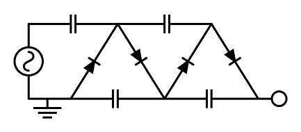
We will be using an antenna to harvest radio signals, and a charge pump design (combining a full-wave rectifier and a voltage multiplier) to charge the energy storage.  That will be used to power an attached device.

The charge pump can be designed in multiple ways.  In the first design, it will consist of a full-wave rectifier and a Dickson voltage multiplier.


An alternative design is to use a Cockroft-Walton voltage multiplier, which takes in AC and converts it to DC while also multiplying the voltage.


[Update 4/15]
I found these videos to be a good starting point (this is part 1/3): http://www.youtube.com/watch?v=_Fuw2V0COEY. We were able to get successful results for harvesting energy with am radio waves.

We have tried a Cockcroft-Walton voltage multiplier but for some reason the voltage in the capacitors is increasing even when there is no antenna attached. I believe it the circuit it self could be acting as an antennae but not entirely sure.


Friday, March 29, 2013

OpenNI + Depth & IR Compression + Pandaboard

[Update 4/14] I do not have access to a pandaboard yet, therefore I am working on this in Ubuntu with a Kinect.

I am looking to compress depth images from a Kinect or Asus Xtion using OpenNI. Currently I am trying to modify NiViewer to capture and save depth frames as images.

See https://groups.google.com/forum/?fromgroups=#!msg/openni-dev/iYtcrrA365U/wEFT2_-mH0wJ
I edited the files as listed on the google groups post. Alternate link: http://gremsi.blogspot.com/2013/04/saving-rgb-and-depth-data-from-kinect.html

Install OpenCV: http://mitchtech.net/raspberry-pi-opencv/

Edit the make file for NiViewer using this: http://ubuntuforums.org/showthread.php?t=1895678

[Update 4/7]
I had a little trouble with the makefile for NiViewer using the link above. Here is what I have for  OpenNI/Platform/Linux/Build/Samples/NiViewer/Makefile


include ../../Common/CommonDefs.mak
BIN_DIR = ../../../Bin
INC_DIRS = \
../../../../../Include \
../../../../../Samples/NiViewer \
/usr/local/lib \
/usr/local/include/opencv
SRC_FILES = ../../../../../Samples/NiViewer/*.cpp
ifeq ("$(OSTYPE)","Darwin")
LDFLAGS += -framework OpenGL -framework GLUT
else
USED_LIBS += glut GL opencv_core opencv_highgui
endif
USED_LIBS += OpenNI
EXE_NAME = NiViewer
CFLAGS        = -pipe -O2 -I/usr/local/include/opencv  -D_REENTRANT $(DEFINES)
CXXFLAGS      = -pipe -O2 -I/usr/local/include/opencv  -D_REENTRANT $(DEFINES)
include ../../Common/CommonCppMakefile


[Update 4/14]
I ran NiViewer, right click and start capture. So as of now, it saves depth images (in OpenNI/Platform/Linux/Bin/(your platform)/CaptureFrames). Remember to create the CapturedFrames folder.

Now, I want it to start capturing as soon as I ran the program so I edited the NiViewer.cpp file to this:

Comment this part out in the main method (the part that handles the user interface):
reshaper.zNear = 1;
reshaper.zFar = 100;

glut_add_interactor(&reshaper);
cb.mouse_function = MouseCallback;
cb.motion_function = MotionCallback;
cb.passive_motion_function = MotionCallback;
cb.keyboard_function = KeyboardCallback;
cb.reshape_function = ReshapeCallback;
glut_add_interactor(&cb);
glutInit(&argc, argv);
glutInitDisplayString("stencil double rgb");
glutInitWindowSize(WIN_SIZE_X, WIN_SIZE_Y);
glutCreateWindow("OpenNI Viewer");
glutFullScreen();
glutSetCursor(GLUT_CURSOR_NONE);
init_opengl();
glut_helpers_initialize();
glutIdleFunc(IdleCallback);
glutDisplayFunc(drawFrame);
drawInit();
createKeyboardMap();
createMenu();
atexit(onExit);
glutMainLoop();
 before the audioShutdown() command is called, I added these lines:

captureStart(0);
int i = 0;
while (i<10)
{
captureFrame();
i++;
}
captureStop(0);
I compiled and ran NiViewer, but I was only getting blank images. This is because the saveFrame_depth() function (from the google groups post) is using a Linear Histogram. It seems that the calculateHistogram method needs to be called before the Linear Histogram is used. Before, drawFrame() was calling the calculateHistogram function and that is why it worked. I just wanted to see if this worked in general so inside the saveFrame_depth() function, there is a line that says switch(g_DrawConfig.Streams.Depth.Coloring), change this to switch(PSYCHEDELIC); Now I am able to see something in my saved depth image.

[Update 4/17]
I wanted to see how much space it would take for depth data to be stored without any compression. I first started out writing the depth values to a binary file (in plain ascii). This is pretty simple but I am just writing everything out incase if anyone is confused. To do this, I created a new file in the beginning of the saveFrame_depth function:
ofstream myfile;
myfile.open("depthData_ascii");
Then inside the nested for loops (after the switch case statements), you will see data being assigned to red, blue and green pointers (e.g. Bptr[nX] = nBlue and etc). I added these lines under the red, green, blue pointer assignments:
myfile << *pDepth
myfile << " "; 
The lines above should be inside the 2nd for loop. Then I added
myfile << "\n" 
at the end of the first for loop. So basically it should look like this:

saveFrame_depth(...)
{
   ofstream myfile;
   myfile.open("depthData_ascii");
   //code
   for(...)
   {
      for(...)
      {
         //code
         myfile << *pDepth
         myfile << " ";
      }
      myfile << "\n"
   } 
   myfile.close()
   //code 

This file seems to take up around 1.2 mb of space per frame.

[Update 4/21]
Saving it as a simple binary file seems to take up too much space. 1.2mb * 30fps * 60seconds/min * 60mins/hr is 126.562gb per hour. I tried to save the depth data inside a png as 16bit unsigned short integers. To do this,  create a new matrix at the beginning of saveFrame_depth file. The dimensions of the matrix should be pDepthMD->YRes() by pDepthMD->XRes(). Instead of creating it as an 8bit unsigned, do 16bit unsigned (CV_16U). The code for this would look like:
cv::Mat depthArray = cv::Mat(pDepthMD->YRes(), pDepthMD->XRes(), CV_16U)
Inside the first for loop, there are RGB pointers being created with the colorArr variable. Create a pointer for for your depthArray in that same location.
uchar* depthArrayPtr = depthArray.ptr<uchar>(nY); 
ushort* depthArrayPtr = depthArray.ptr<ushort>(nY);
 edit: I had to use ushort for the pointer type. Im not sure exactly why because the pointer type should stay the same length whether or not we are creating a depthArray of 16bit unsigned short or 8bit unsigned char. But using ushort works, where as if I used uchar it saved the image on the left half.

image when using uchar*
image when using  ushort*


Inside the second for loop (toward the end of it), there are values being assigned to the locations of those pointers (e.g. Bptr[nX] = nBlue), under those lines, add this:
depthArrayPtr[nX] = *pDepth
All that is happening is, I am storing the raw depth value in an matrix. Save this array as a png image (add these lines at the end of the function saveFrame_depth):
vector<int> compression_params;
compression_params.push_back(CV_IMWRITE_PNG_COMPRESSION);
compression_params.push_back(0);
imwrite(str_aux_raw, depthArray, compression_params);
I had to #include "cv.h", "highgui.h", <vector>, <iostream>, and <fstream>. In addition to that, I added using namespace std; after my include statements.

This will save the image as a png and it should have the original depth values. The total size comes out to be around 100kb - 200kb (depending on the depth image).

124kb


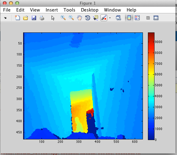
To see if you are saving your png image correctly and the values are correct, I used MatLab. In MatLab enter this command:
image = imread('/path/to/image.png'); imagesc(image); colorbar;
This should give you a scale of the values represented in your depth image. You could even click Tools->Data Cursor (in the image window) and select a point in that image to get the specific value at that point.


other information: ~1 min of recording depth as a png (with 0 compression) =  14.5mb. It could be that it is not doing 30fps. There were over all of 117 images so thats about 2 images/frames per second.

[Update 4/21]
I am now trying to get IR data and store it into the image. I found some code that could help: https://groups.google.com/d/msg/openni-dev/ytk-dRPDkoM/XKgoIhOxsv8J

[Update 4/26]
I dont think the code is the problem here, because viewing IR data is not working at all in NiViewer. However I do have some information about compression with depth data. I was able to use PNG_COMPRESSION in imwrite and set that value to 50. The image lowered about 10kb (so not that much). However if I had a binary/text file of 1.5mb and zipped that, it would go down to 67kb. So maybe I could use gzip to zip the files as I am saving them.

Updating...

Thursday, March 28, 2013

Saving RGB and Depth Data from Kinect as an Image (with OpenNI)


This is not my work, I am reposting it just incase if it gets removed. Source: https://groups.google.com/forum/?fromgroups=#!msg/openni-dev/iYtcrrA365U/wEFT2_-mH0wJ

Hi all,
I am working on foreground segmentation using kinect. I needed to
extract the color and depth images in a synchronized and registerd way
and This thread has been very useful for me. I write you the code I
have used to do it, if someone need to do the same:

I started modifying the NiViewer sample code you can find in:
/OpenNI/Platform/Linux-x86/Redist/Samples/NiViewer

Then, I modified some of their files to achieve the .jpg recording
jointly with the .oni file. To save the images, I have used opencv
library.

extract RGB images  (in Device.cpp):

 //new includes:
#include "cv.h"
#include "highgui.h"
#include "sstream"
#include "string"

//jaume. New function to save RGB frames in jpg format.

void saveFrame_RGB(int num)
{
    cv::Mat colorArr[3];
    cv::Mat colorImage;
    const XnRGB24Pixel* pImageRow;
    const XnRGB24Pixel* pPixel;

//     ImageMetaData* g_ImageMD = getImageMetaData();
    g_Image.GetMetaData(g_ImageMD);
    pImageRow = g_ImageMD.RGB24Data();

    colorArr[0] = cv::Mat(g_ImageMD.YRes(),g_ImageMD.XRes(),CV_8U);
    colorArr[1] = cv::Mat(g_ImageMD.YRes(),g_ImageMD.XRes(),CV_8U);
    colorArr[2] = cv::Mat(g_ImageMD.YRes(),g_ImageMD.XRes(),CV_8U);

    for (int y=0; y<g_ImageMD.YRes(); y++)
    {
      pPixel = pImageRow;
      uchar* Bptr = colorArr[0].ptr<uchar>(y);
      uchar* Gptr = colorArr[1].ptr<uchar>(y);
      uchar* Rptr = colorArr[2].ptr<uchar>(y);
              for(int x=0;x<g_ImageMD.XRes();++x , ++pPixel)
              {
                      Bptr[x] = pPixel->nBlue;
                      Gptr[x] = pPixel->nGreen;
                      Rptr[x] = pPixel->nRed;
              }
      pImageRow += g_ImageMD.XRes();
    }
    cv::merge(colorArr,3,colorImage);

    char framenumber[10];
    sprintf(framenumber,"%06d",num);


    std::stringstream ss;
    std::string str_frame_number;
//     char c = 'a';
    ss << framenumber;
    ss >> str_frame_number;

    std::string str_aux = "CapturedFrames/image_RGB_"+
str_frame_number +".jpg";
    IplImage bgrIpl = colorImage;                      // create a
IplImage header for the cv::Mat bgrImage
    cvSaveImage(str_aux.c_str(),&bgrIpl);                // save it with the
old

}

extract Depth images  (in Draw.cpp):

 //new includes:
#include "cv.h"
#include "highgui.h"

//jaume. New function to save depth map in jpg format. I have based
this implementation on the draw images function.

void saveFrame_depth(int num)
{
  const DepthMetaData* pDepthMD = getDepthMetaData();
  const XnDepthPixel* pDepth = pDepthMD->Data();
  XN_ASSERT(pDepth);

   cv::Mat depthImage;
   cv::Mat colorArr[3];

    colorArr[0] = cv::Mat(pDepthMD->YRes(),pDepthMD->XRes(),CV_8U);
    colorArr[1] = cv::Mat(pDepthMD->YRes(),pDepthMD->XRes(),CV_8U);
    colorArr[2] = cv::Mat(pDepthMD->YRes(),pDepthMD->XRes(),CV_8U);


  for (XnUInt16 nY = pDepthMD->YOffset(); nY < pDepthMD->YRes() +
pDepthMD->YOffset(); nY++)
  {
    XnUInt8* pTexture = TextureMapGetLine(&g_texDepth, nY) + pDepthMD-
>XOffset()*4;

      uchar* Bptr = colorArr[0].ptr<uchar>(nY);
      uchar* Gptr = colorArr[1].ptr<uchar>(nY);
      uchar* Rptr = colorArr[2].ptr<uchar>(nY);

    for (XnUInt16 nX = 0; nX < pDepthMD->XRes(); nX++, pDepth++,
pTexture+=4)
    {
            XnUInt8 nRed = 0;
            XnUInt8 nGreen = 0;
            XnUInt8 nBlue = 0;
            XnUInt8 nAlpha = g_DrawConfig.Streams.Depth.fTransparency*255;

            XnUInt16 nColIndex;

            switch (g_DrawConfig.Streams.Depth.Coloring)
            {
            case LINEAR_HISTOGRAM:
                    nBlue = nRed = nGreen = g_pDepthHist[*pDepth]*255;
                    break;
            case PSYCHEDELIC_SHADES:
                    nAlpha *= (((XnFloat)(*pDepth % 10) / 20) + 0.5);
            case PSYCHEDELIC:

                    switch ((*pDepth/10) % 10)
                    {
                    case 0:
                            nRed = 255;
                            break;
                    case 1:
                            nGreen = 255;
                            break;
                    case 2:
                            nBlue = 255;
                            break;
                    case 3:
                            nRed = 255;
                            nGreen = 255;
                            break;
                    case 4:
                            nGreen = 255;
                            nBlue = 255;
                            break;
                    case 5:
                            nRed = 255;
                            nBlue = 255;
                            break;
                    case 6:
                            nRed = 255;
                            nGreen = 255;
                            nBlue = 255;
                            break;
                    case 7:
                            nRed = 127;
                            nBlue = 255;
                            break;
                    case 8:
                            nRed = 255;
                            nBlue = 127;
                            break;
                    case 9:
                            nRed = 127;
                            nGreen = 255;
                            break;
                    }
                    break;
            case RAINBOW:
                    nColIndex = (XnUInt16)((*pDepth / (g_fMaxDepth / 256)));
                    nRed = PalletIntsR[nColIndex];
                    nGreen = PalletIntsG[nColIndex];
                    nBlue = PalletIntsB[nColIndex];
                    break;
            case CYCLIC_RAINBOW:
                    nColIndex = (*pDepth % 256);
                    nRed = PalletIntsR[nColIndex];
                    nGreen = PalletIntsG[nColIndex];
                    nBlue = PalletIntsB[nColIndex];
                    break;
            }


            Bptr[nX] = nBlue ;
            Gptr[nX] = nGreen;
            Rptr[nX] = nRed;


    }
  }

   cv::merge(colorArr,3, depthImage);


    char framenumber[10];
    sprintf(framenumber,"%06d",num);


    std::stringstream ss;
    std::string str_frame_number;

    ss << framenumber;
    ss >> str_frame_number;

   //CapturedFrames folder must exist!!!
    std::string str_aux = "CapturedFrames/image_depth_"+
str_frame_number +".jpg";

   IplImage bgrIpl = depthImage;                      // create a
IplImage header for the cv::Mat bgrImage
   cvSaveImage(str_aux.c_str(),&bgrIpl);                // save it with the
old

}


File where I use these new functionalities: Capture.cpp.


//New include:
#include <iostream>

//Function modified to save frames in jpg format:
XnStatus captureFrame()
{
        XnStatus nRetVal = XN_STATUS_OK;
        if (g_Capture.State == SHOULD_CAPTURE)
        {
                XnUInt64 nNow;
                xnOSGetTimeStamp(&nNow);
                nNow /= 1000;

                if (nNow >= g_Capture.nStartOn)
                {
                        g_Capture.nCapturedFrames = 0;
                        g_Capture.State = CAPTURING;
                }
        }

        if (g_Capture.State == CAPTURING)
        {
                nRetVal = g_Capture.pRecorder->Record();
                XN_IS_STATUS_OK(nRetVal);

                //start.jaume
                saveFrame_RGB(g_Capture.nCapturedFrames);
                saveFrame_depth(g_Capture.nCapturedFrames);
                //end.jaume

                g_Capture.nCapturedFrames++;
        }
        return XN_STATUS_OK;
}

To test the code, you must execute the new NiViewer app, and use the
options Capture->start that appear just clicking in the left mouse
button.

It's all, I hope this code will be useful.

Jaume